Planning Outputs and Inputs for a Patchbay

I have been working on the future studio layout and having finished the hardware positions I turned my attention to the cabling and patchbays.

This is want I want to avoid

For patchbays I have an ART P16 Patch Bay, and two NYS-SPP-L1 Neutrik Patchbays. The ART P16 is simple as it will be used for Microphone inputs feeding directly to the Allen & Heath mixing desk MIC inputs.

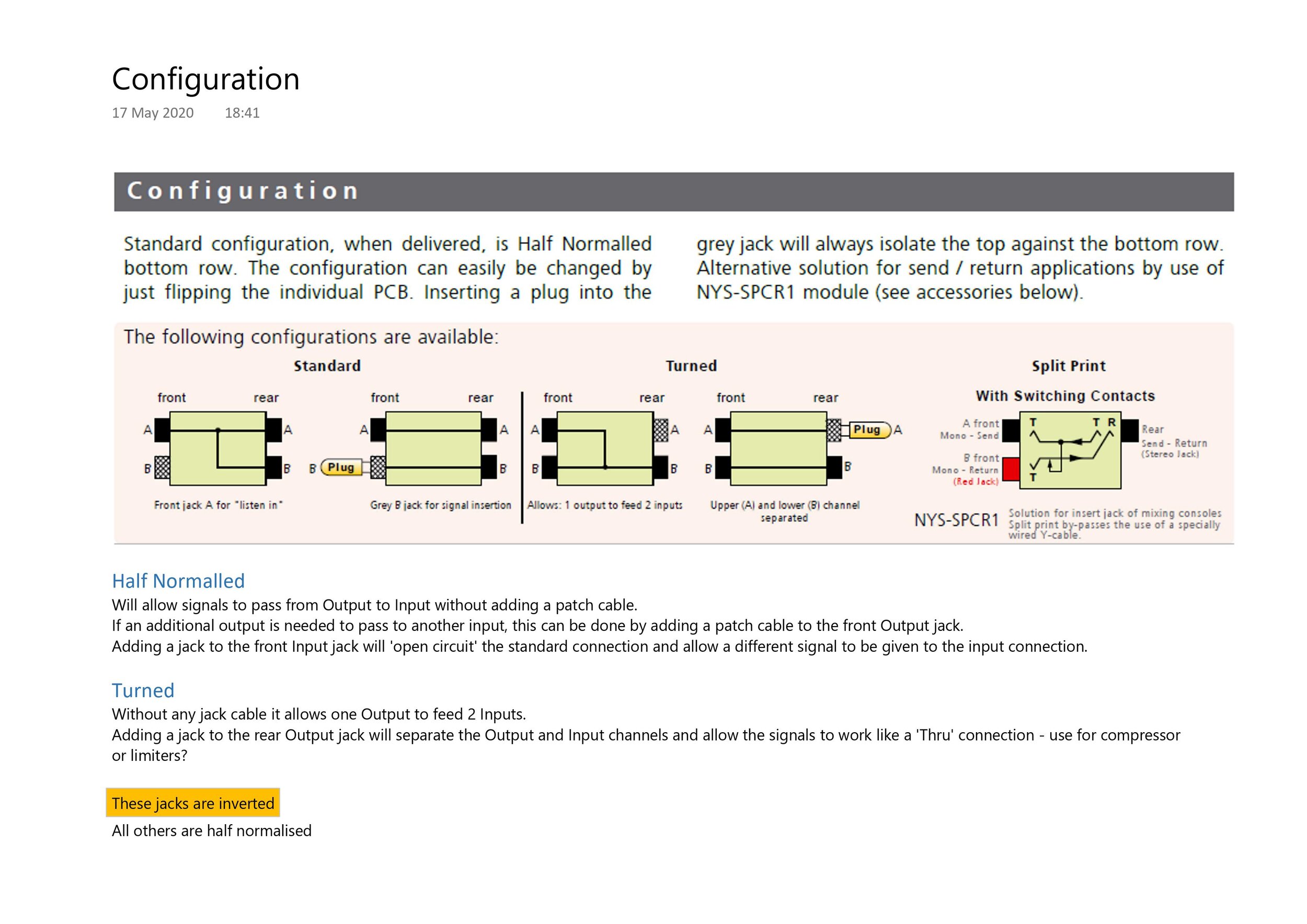
The Neutrik patchbays have a default half normalised setting, but when the PCB is turned they allow a ‘straight through’ connection which is useful for some equipment.

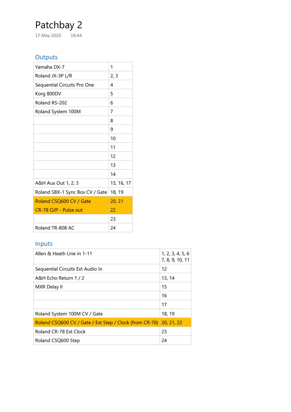
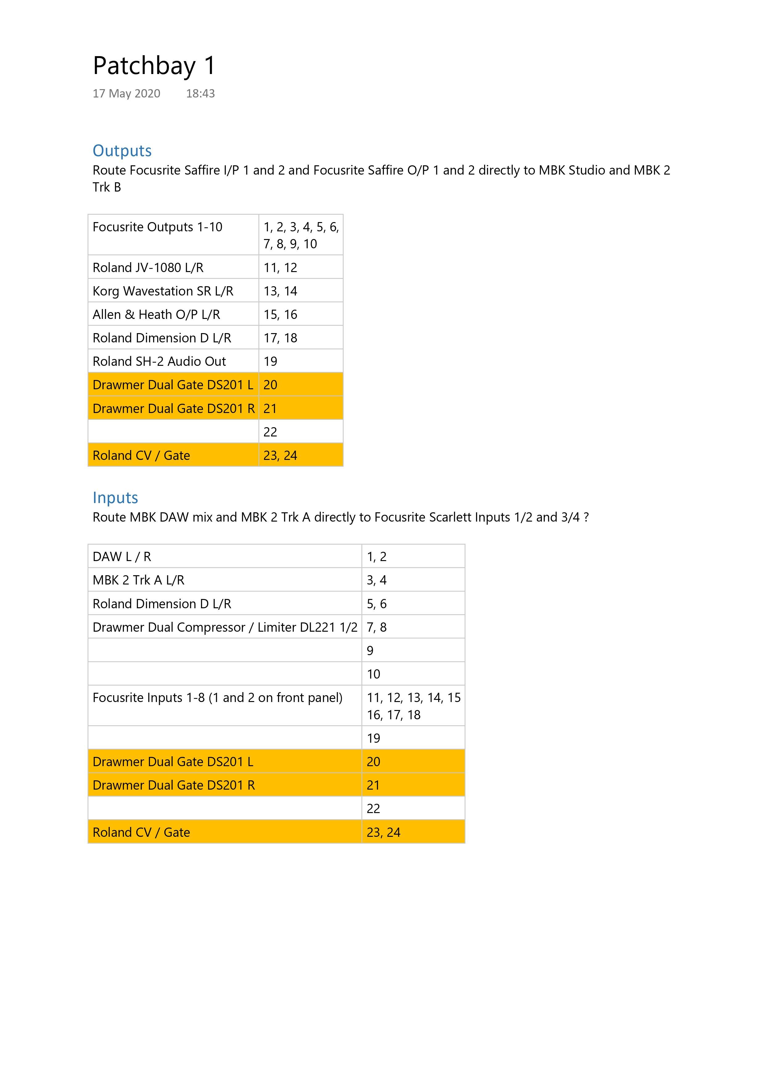
The Configuration and the planning for Patchbay 1 and Patchbay 2 is shown below as planned today; I’m pretty sure that something will change somewhere.
Planning the design and build of a sound Recording Studio

Thank-you social isolation! I have finally had enough time to begin the re-design of the #recording studio. Whilst I have tried many high tech methods in the past, using design software and 3D modelling, this time I have gone for a low tech and tactile approach using a scale model and up-cycling some of the cardboard that has acumulated of the last few weeks.

The result so far is shown here.

2201 Recording - studio design model

The blue bottom right is the glass door into the studio and the large black square is the mandatory black leather chair. The model is a 10:1 ratio which represents the 6m x 4m studio space. I haven’t yet planned the acoustic panels.

 
thon studio side rack xl 10U.jpg

The Thon Racks hold various rack mounted equipment including power conditioning and patch bays. See my previous article about patch bays here.

The large Thon Studio rack with the Roland TR-808 on top includes two power conditioning units and a patch bay which includes control voltage (CV) jacks to supply the analogue synthesizers on that side of the studio.

Currently I’m working on the power supply layout coming from the four power conditioners and backup power supply. After that I’ll check that the audio and digital signal flow (the path an audio signal must travel through your gear, from beginning to end) is feasible with the various cable looms that I have.

Signal flow between sound cards and Mackie Big Knob

Signal flow between Allen & Heath 168 mixer and (mainly) analogue equipment

In the future I will cover

  1. Structural and acoustic design

    1. I have tried to get as close to ‘The Golden Ratio’ as possible which is nicely explained here https://www.mathsisfun.com/numbers/golden-ratio.html

      The golden ratio (symbol is the Greek letter "phi" shown at left) is a special number approximately equal to 1.618. We find the golden ratio when we divide a line into two parts so that:

      the whole length divided by the long part

      is also equal to

      the long part divided by the short part

      e.g. Studio size of 6000 x 3710 is good (=1.618)

  2. Construction and fit

  3. Air conditioning design - how it integrates with acoustic and interior designs

The exciting life of a Patchbay

I can’t believe that I haven’t written about using #PatchBays in the recording studio before! So let’s remedy that omission straight away with some essential points about how to use them.

Old style patchbay

At first, knowing how to use a patchbay seems like it would require a textbook, a doctorate in electrical engineering, an IQ of 300, and some magical incantations. The different types of patchbays available (analogue or digital, ordinary ¼ inch, long frame ¼ inch, bantam 3/8 inch…) and their configuration (Normalized, Half-normalized or Thru) adds to the confusion.

Patchbays offer flexibility.

Once you know the fundamental rules patchbays offer a simple way to connect one piece of equipment to another. As long as you understand how they work, there’s nothing to panic about.

Rule 1 - the top jacks are for Outputs

Always envision the audio signal going into the top back jack and coming out of the top front jack. The top jacks are called output jacks because the top back jack receives the output from whatever piece of gear you're using and spits it out of the front top jack.  If you follow this rule (as do all professionals) you will only be dealing with the outputted signal when you're patching the top row.  In most cases (keep it simple for now), the signal comes out of the keyboard or microphone, goes into the top back, and comes out of the top front. The outputs are top only, back-to-front.

Rule 2 - bottom jacks are for Inputs

So now you have your signal coming out of the top row on the front of your panel.  You plug in a patch cable and route it to the bottom row, which is the exact opposite of the top row.  It is only for inputs on your gear.  The signal flows into the cable, into a bottom front jack, and out of the bottom back jack and into an input in another piece of gear. The inputs are bottom only, front-to-back.

Rule 3 - Connections only occur top-to-bottom

Since outputs are on top and inputs are on bottom, you will never need to or want to patch a cable from a top jack to another top jack.  The same goes for bottom to bottom connections.  They don't happen. Patch cables only ever connect a top jack to a bottom jack.


Normal, Half-Normal, & Thru Modes

There are three ways the jacks are wired together that represent the three main modes of usage. These are known as #PatchbayModes. Some patch bays let you change modes with a switch. Some require you to physically manipulate the jacks. Some don't let you change the mode.

It's fine, though. You can stick with Normal mode and be perfectly happy, you'll just need more patch cables. But if you learn to use the other two modes you can really dial in the magic to save you effort and cabling time. Let's discuss each mode:

  1. Normal Mode:  The top output jack sends the audio signal to the bottom input jack until a patch cable is inserted. The cable interrupts that signal path and intercepts it, sending it through the cable only.

  2. Half-Normal Mode: The top output jack sends the audio signal to the bottom jack even if you've inserted a patch cable. This lets you split the signal to send to two inputs.

  3. Thru Mode: The top output jacks only sends the signal to each other, back-to-front. Unless you plug in a cable to send the signal to an input, the signal hits a dead-end.

For the most part, Normal Mode and Half-Normal mode will take care of all of your needs. Most of us hang out in Normal Mode, where we record and do simple mixing and clean-up equalization work out of the box and then send the signal to the interface, where we finish up the mixing in the box (meaning in a software DAW like Pro Tools or Logic Pro).

Patchbay rules

Patchbay modes

Aux Insert / Send

Two TRS insert jacks on your mixer will only get you two outs. If you are using it as a direct out with just a TS cable (instead of the standard insert y cable) you are only using the send (from the mixer) and the other half, the return, is unused. An insert is a loop out from a channel or bus and back in.

Here is a wiring diagram that might make it clearer

Connecting to mixer Insert send points

Using the Drawmer DS201 as an example this shows how to connect the dual gate to the insert points of the mixer or insert of an individual channel.


CV’s

Remember, the patchbay can also include CV’s to use with your modular setup !!!