Planning Outputs and Inputs for a Patchbay

I have been working on the future studio layout and having finished the hardware positions I turned my attention to the cabling and patchbays.

This is want I want to avoid

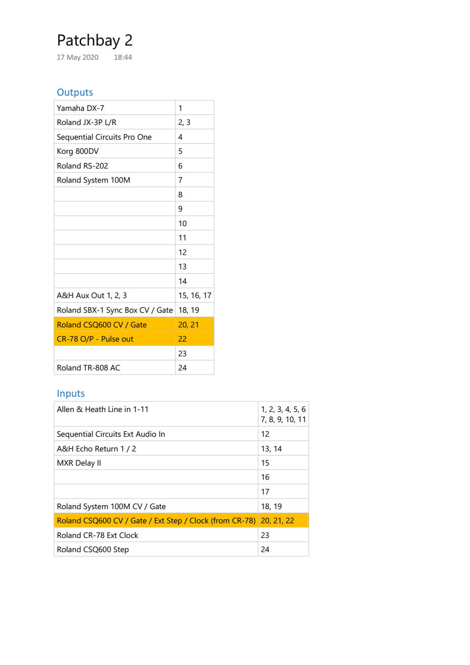
For patchbays I have an ART P16 Patch Bay, and two NYS-SPP-L1 Neutrik Patchbays. The ART P16 is simple as it will be used for Microphone inputs feeding directly to the Allen & Heath mixing desk MIC inputs.

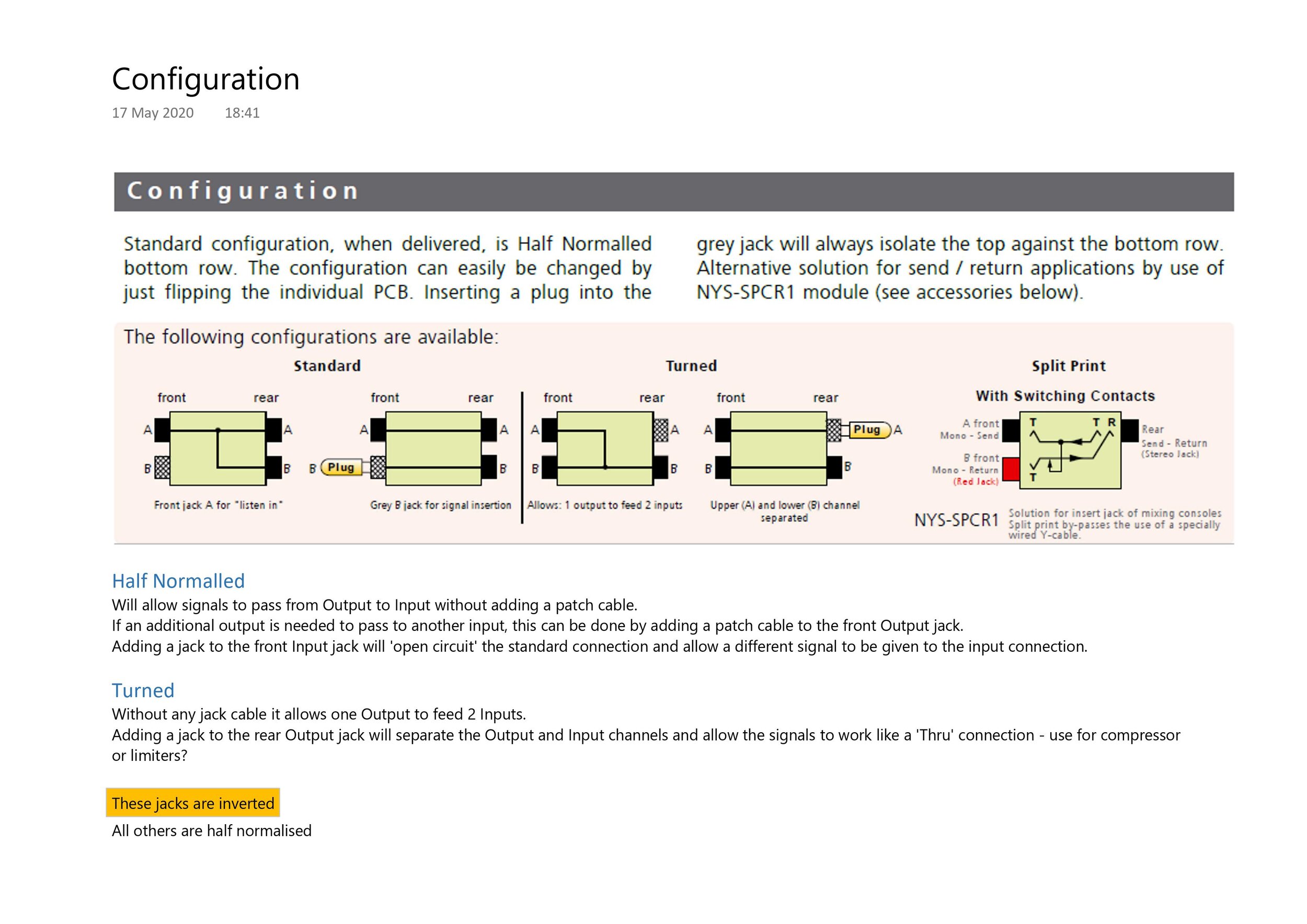
The Neutrik patchbays have a default half normalised setting, but when the PCB is turned they allow a ‘straight through’ connection which is useful for some equipment.

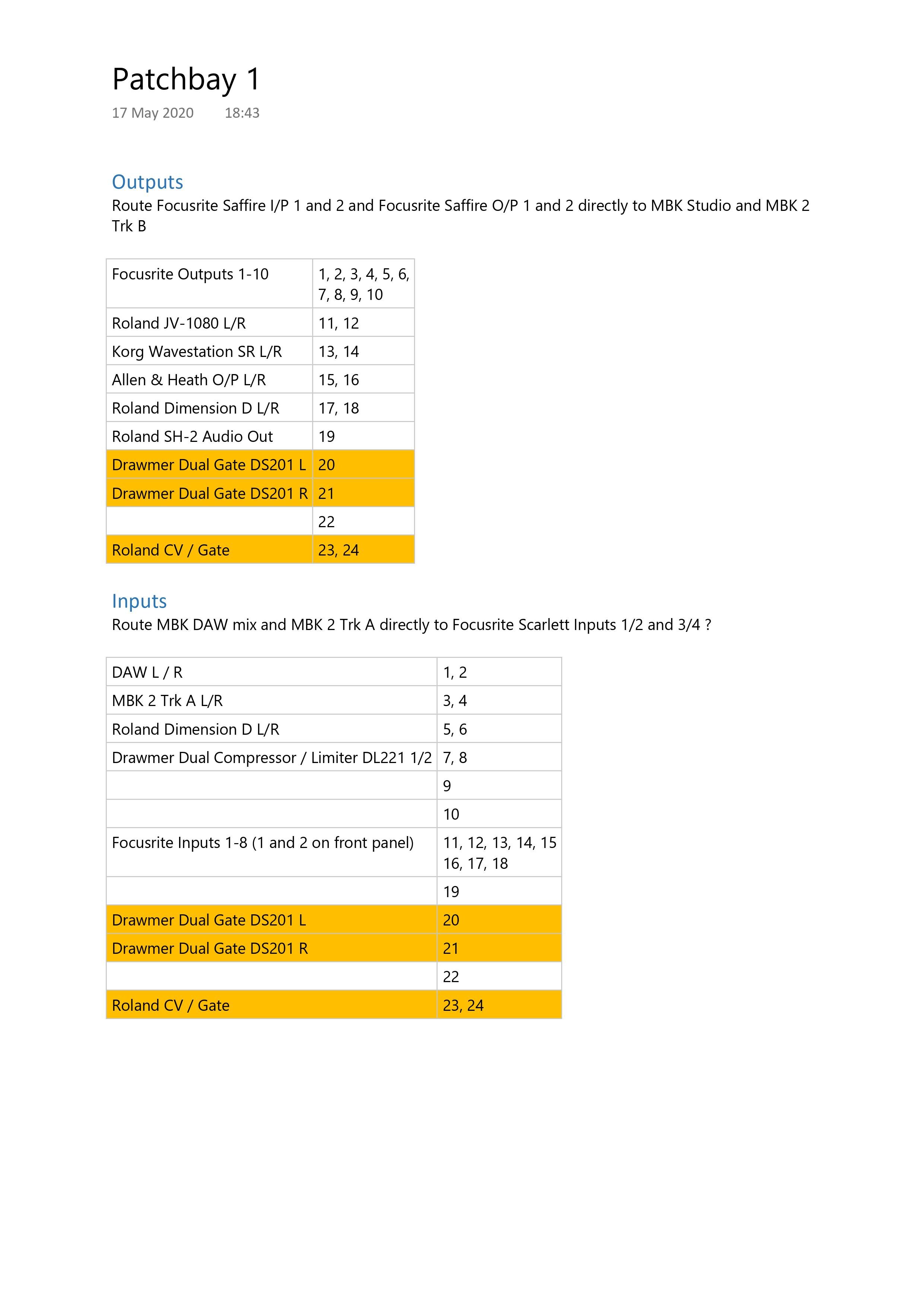
The Configuration and the planning for Patchbay 1 and Patchbay 2 is shown below as planned today; I’m pretty sure that something will change somewhere.
Planning the design and build of a sound Recording Studio

Thank-you social isolation! I have finally had enough time to begin the re-design of the #recording studio. Whilst I have tried many high tech methods in the past, using design software and 3D modelling, this time I have gone for a low tech and tactile approach using a scale model and up-cycling some of the cardboard that has acumulated of the last few weeks.

The result so far is shown here.

2201 Recording - studio design model

The blue bottom right is the glass door into the studio and the large black square is the mandatory black leather chair. The model is a 10:1 ratio which represents the 6m x 4m studio space. I haven’t yet planned the acoustic panels.

 
thon studio side rack xl 10U.jpg

The Thon Racks hold various rack mounted equipment including power conditioning and patch bays. See my previous article about patch bays here.

The large Thon Studio rack with the Roland TR-808 on top includes two power conditioning units and a patch bay which includes control voltage (CV) jacks to supply the analogue synthesizers on that side of the studio.

Currently I’m working on the power supply layout coming from the four power conditioners and backup power supply. After that I’ll check that the audio and digital signal flow (the path an audio signal must travel through your gear, from beginning to end) is feasible with the various cable looms that I have.

Signal flow between sound cards and Mackie Big Knob

Signal flow between Allen & Heath 168 mixer and (mainly) analogue equipment

In the future I will cover

  1. Structural and acoustic design

    1. I have tried to get as close to ‘The Golden Ratio’ as possible which is nicely explained here https://www.mathsisfun.com/numbers/golden-ratio.html

      The golden ratio (symbol is the Greek letter "phi" shown at left) is a special number approximately equal to 1.618. We find the golden ratio when we divide a line into two parts so that:

      the whole length divided by the long part

      is also equal to

      the long part divided by the short part

      e.g. Studio size of 6000 x 3710 is good (=1.618)

  2. Construction and fit

  3. Air conditioning design - how it integrates with acoustic and interior designs